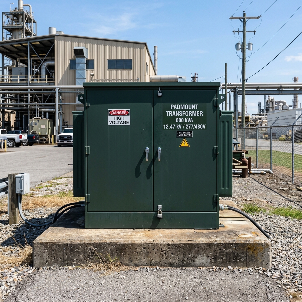
In modern underground medium-voltage electrical distribution networks, compartmental-type, pad-mounted transformers built to IEEE C57.12.34 and ANSI C57.12.28 standards represent the benchmark for utility distribution, master-planned commercial complexes, industrial parks, and solar gathering fields. Unlike conventional substation transformers enclosed inside locked switchyard fencing, padmount transformers are installed directly in public-accessible areas, making tamper-resistance and safe operator access paramount engineering imperatives.
1. Tamper-Resistant Enclosure Architecture (ANSI C57.12.28)
To prevent unauthorized personnel, pedestrians, or vandals from accessing energized medium-voltage connections, IEEE C57.12.34 enforces strict structural enclosure criteria:
- Compartmentalized Barrier Separation: The enclosure is divided into two distinct compartments: High-Voltage (HV) on the left and Low-Voltage (LV) on the right, separated by a full-height steel barrier.
- Interlocked Access Sequence: The low-voltage compartment door must be unlocked and opened first with a recessed captive penta-head bolt before the high-voltage door latch can be released.
- Pry-Bar Resistance Test: The cabinet joints, sills, and door edges undergo rigorous mechanical pry-testing with cold-steel crowbars without opening any gap greater than 6.35 mm (1/4 inch).
- Slanted Roof Water Shedding: The cabinet top hood is sloped forward to ensure rainwater runoff and prevent moisture accumulation.
2. Electrical Configurations: Loop-Feed vs. Radial-Feed
Understanding the difference between loop-feed and radial-feed configurations is crucial for utility distribution planning:
⚡ IEEE C57.12.34 Terminal Bushing Comparison
| Parameter | Loop-Feed Configuration | Radial-Feed Configuration |
|---|---|---|
| High-Voltage Bushings | 6 Bushing Wells (2 per phase: A1/A2, B1/B2, C1/C2) | 3 Bushing Wells (1 per phase: H1, H2, H3) |
| Network Redundancy | Allows sectionalizing and back-feeding from either side of underground loop | Dead-end spur line; power interruption requires taking circuit out of service |
| Internal Loadbreak Switch | 4-position T-blade or V-blade switch (Loop A, Loop B, Open, Both) | 2-position ON/OFF loadbreak switch |
3. Coordinated Two-Stage Overcurrent Protection
SOTEK IEEE C57.12.34 padmount units feature coordinated dual overcurrent fusing systems immersed in the transformer tank:
- Bay-O-Net Oil-Immersed Fuses (Thermal & Overload): Externally removable with an insulated hotstick, calibrated to blow during prolonged overloads or low-level internal secondary faults.
- Partial-Range Current-Limiting Fuses (Backup CLF): Wired in series with the Bay-O-Net fuses inside the tank to safely interrupt catastrophic high-magnitude faults (up to 50,000 A symmetrical) in less than half a cycle, preventing tank rupture.
With dozens of units operating across major utility grids in the Philippines (e.g., Visayan Electric and Davao Light), SOTEK provides full type-test certificates and customizable pad-mounted units from 75 kVA up to 5,000 kVA (up to 34.5 kV).
