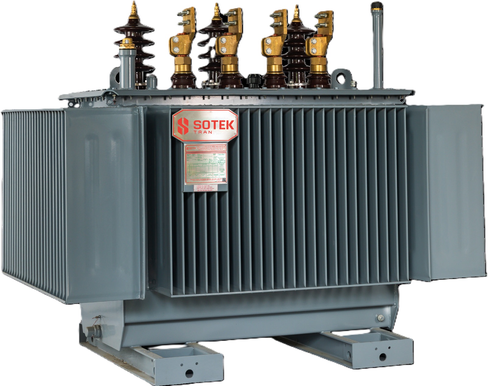
Utility-scale solar photovoltaic (PV) power plants and Battery Energy Storage Systems (BESS) impose unique operational, thermal, and electrical stresses on medium-voltage (MV) step-up transformers that conventional distribution grid units are never designed to endure. In modern renewable generating stations, step-up transformers operate at the critical junction between low-voltage power conversion systems (PCS / solar central inverters) and the high-voltage transmission interconnect (typically 22 kV, 34.5 kV, or 35 kV).
To ensure 25+ year field reliability without premature dielectric breakdown or thermal degradation, consulting engineers and EPC contractors must rigorously address three core engineering challenges: inverter harmonics (K-factor design), dual-input split-winding electro-magnetic isolation, and transient overvoltage mitigation caused by vacuum circuit breaker (VCB) switching.
1. Managing Inverter Harmonics: K-Factor & Stray-Loss Mitigation
Modern grid-tied pulse-width modulated (PWM) solar inverters generate non-sinusoidal currents rich in high-frequency harmonics (predominantly 5th, 7th, 11th, and 13th order). In a standard distribution transformer, high-frequency harmonic currents dramatically amplify stray load losses, specifically:
- Winding Eddy Current Losses ($P_{EC}$): Scale with the square of the harmonic frequency ($f^2$) and the square of the harmonic current ($I_h^2$).
- Other Stray Losses ($P_{OSL}$): Generated by harmonic leakage flux impinging on structural tie plates, core clamps, and tank walls.
SOTEK engineers solar step-up transformers with designated K-factor ratings (typically K-4 to K-9) in accordance with IEEE C57.110. To prevent localized hot-spot overheating:
- Primary windings utilize continuously transposed conductors (CTC) or multi-strand transposed copper strips with epoxy bonding to suppress eddy currents.
- Core clamping frames are fabricated from non-magnetic stainless steel alloys to eliminate eddy-current hotspots caused by stray magnetic fringing flux.
- Internal winding thermal sensors (PT100 RTDs) are placed at calculated electromagnetic hotspot nodes for real-time SCADA telemetry.
2. Multi-Inverter Integration: Dual Low-Voltage Split Winding Design
To reduce substation footprint and balance-of-system (BOS) capital costs, modern utility-scale solar skids connect two, three, or four separate inverter blocks to a single step-up transformer. This requires a Split-Winding (Dual Secondary) architecture (e.g., 0.8 kV / 0.8 kV to 35 kV).
A critical engineering parameter is the Cross-Impedance ($Z_{LV1-LV2}$) between the two low-voltage windings. If the electromagnetic coupling between the two secondary windings is too tight, circulating harmonic currents and ground-fault transfer between inverters can trip inverter protection relays simultaneously.
⚡ SOTEK Axial vs. Radial Split-Winding Comparison
| Design Topology | Decoupling Impedance ($Z_{LV1-LV2}$) | Short-Circuit Mechanical Rigidity | Optimal Solar Application |
|---|---|---|---|
| Axial Split (Stacked) | High ($> 2.5 imes Z_{sc}$) | Requires braced intermediate clamping | Central inverters with independent DC arrays |
| Radial Split (Concentric) | Moderate ($1.8 – 2.2 imes Z_{sc}$) | Maximum mechanical hoop-stress strength | Compact skid stations / String inverter clusters |
3. SOTEK Solar & BESS Step-Up Transformer Specifications
Manufactured at SOTEK’s 18,500 m² Tien Son High-Voltage Facility (Bac Ninh, Vietnam), each solar step-up transformer undergoes full routine and type testing verified by our ISO/IEC 17025 (VILAS 1183) Accredited Laboratory:
| Rated Capacity | 1,000 kVA to 6,300 kVA (Custom multi-MVA skid ratings) |
| High-Voltage Ratings | 11 kV, 22 kV, 33 kV, 34.5 kV, 35 kV (BIL up to 200 kV) |
| Low-Voltage Ratings | 0.4 kV, 0.6 kV, 0.69 kV, 0.8 kV Dual or Quad Inverter Inputs |
| Electrostatic Shielding | Copper grounding foil between HV and LV to block high-frequency transients |
| Dielectric Fluids | High-grade inhibited mineral oil (IEC 60296) or FR3 Natural Ester Fluid (biodegradable, high flash point 360°C) |
| Corrosion Protection | Hot-dip galvanized corrugated fins or C5-M Heavy Industrial Marine Coating (ISO 12944) |
